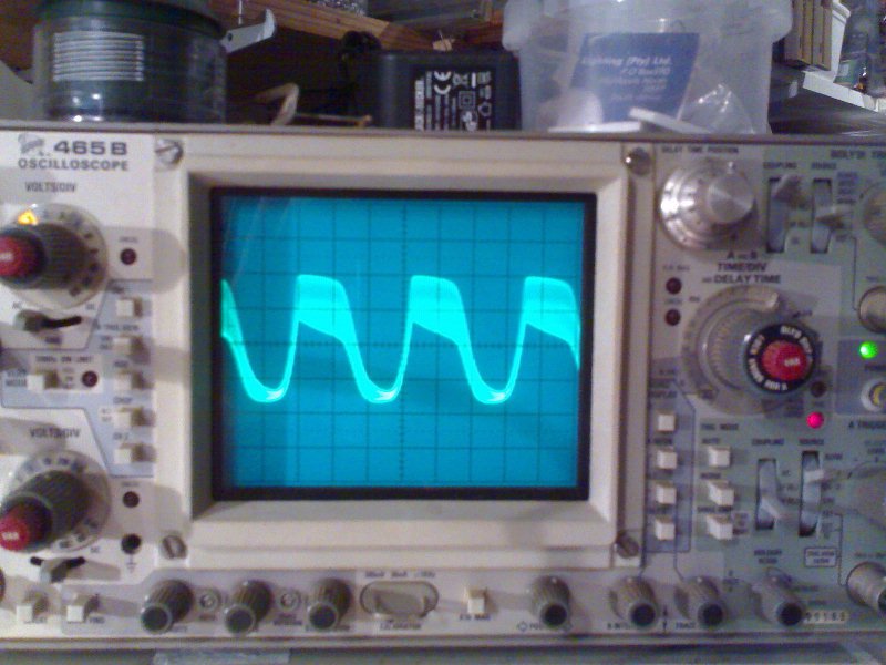
When I connected the oscilloscope to the test point, it showed a sine wave (roughly) of 3.3 divisions of 0.5 micro Seconds per division with a higher frequency on top of that. Oh dear! (or words to that effect)
The Ham-Comp Direct Conversion Receiver
[Based on the previously published DC RX in the Anode of March 2008. The original receiver article appeared in CQ June 1983, page 40, written by Bozidar Pasaric, YU2HL]
Object of this project
To remove some of the obstacles to radio frequency experimentation in South Africa. Obtaining components from junked hardware (scavenging) and experimental construction techniques (home construction/non-laboratory testing).
This "beginners" project will get everyone used to the idea of building and trying out circuits. Ultimately this receiver can be controlled by a PC and tuned to a frequency by a control signal from the PC. The audio signal can be gain/amplitude processed and bandwidth limited by the controlling PC, much the same as the S.D.R. receiver does. The amateur frequency band can also be selected by a control signal from the PC.
We are starting this project from a simple starting point. We shall construct an 80 metre receiver model and adjust the coils to suit the band and sensitivity. Testing and comparisons will be carried out at 'bring and fix' meetings. Construction and testing sessions will be held at the club on the 'open day' / Ham-Comp meetings.
We can also use the 80 metre receiver to test our 80 metre "fox"/beacon, when we get round to building it.
Making the coils
In most of these types of project, the coil making is a critical and sometimes difficult part of the construction. Winding coils is not so much an art as an exercise in care and patience. Winding wires of 46 gauge requires gentle winding and some means of stopping it from escaping the former and making you start all over again. Some constructors recommend background classical music and coffee in quantity before attempting the coil winding.
One of my concerns was the finding of a suitable former for the VFO coil. This should be a rigid and mountable form with no loss component in the material. I suggested at first using a ball-point pen tube and constructed some nice coils this way. Unfortunately with insufficient inductance for the 1.750MHz oscillator. However the coils turned out quite nicely and could be used for higher frequencies.
Note: "cooking" the coil former in the microwave has very little relevance here. A material that gets hot at microwave frequencies would probably have little loss or resistive part at H.F.
Modifications to the original design
First of all I compiled some notes and comments given to me by members.
DC RX Notes
Referring to Fig 2.
1) Oscillator at half-input frequency, means twice the drift.
2) Two diode mixer will have +/-11 dB conversion loss.
3) R1 (3k7) must be a typo. Probably 3k9.
4) R8 (trimmer pot) bias/gain adjustment is bad practice & probably will destroy T2 if shorted.
5) Darlington on R6 (10k) is ridiculous. Input Z of T4 can be 10k+. Redesign this.
6) R7 (1k3) Why not use 1k5 or 1k2?
7) C6 (12pF trimmer) for tuning! Try finding one!
2-18pF trimmer is the only one I have and its not a tuning capacitor.
Rather use an FM transistor radio tuning capacitor in series with 47pF or similar.
8) C6 and L5 tunes to 1750 to 1800kHz, 50kHz in 1800kHz.
small variation in frequency could as easily achieved with a varicap diode on stable voltage.
9) OM Chris raised the point re the C7/C8 being 1nF, which is far too large. Suggested 470pF. [see later notes]
Referring to Fig 4.
1) BB103 (D4) probably difficult to find. Rather use 1N4007 taken from a broken 'energy saver' light bulb (globe in souff afriken).
2) 6V3 Zeners are available, if you search the country. Replace with 7805 with LED in ground connection.
Two things achieved by this; LED lights when power is on.
A very stable 7 Volt (nominal) source to VFO and varicap tuning diode.
3) 330 Ohm resistor is no longer required.
“The circuit she no oscillate!”
Well it wasn't really a surprise but I wondered why. The voltages were close to what I had predicted and calculated. But I could observe no R.F. Oscillation.
The 12 Volt supply was 12.22 Volts. The led was lit and had 1.93 Volts across it. The output of the regulator (7805) was 6.98 Volts. The emitter of the 2N2222A transistor was 0.64 Volts. The base was 1.14 Volts. The collector (checking) was 6.98 Volts.
Back to my revision notes
R3 to be changed for a 47k. This should raise the base to 6.98 / 2 approximately 3.45 Volts and thus the emitter current. So I changed R3 to 47k.
The base went up to 2.89 Volts and the emitter to 2.97 Volts. Whoa! Check that again! Yep, 2.97 Volts. I put my finger onto the base connection, it dropped to 2.63 Volts. A sure sign that the circuit was oscillating.
When
I connected the oscilloscope to the test point, it showed a sine wave
(roughly) of 3.3 divisions of 0.5 micro Seconds per division with a
higher frequency on top of that. Oh dear! (or words to that effect)
The picture from the 'scope trace is one of “squegging”. The circuit now has too high a gain at two frequencies. So one modulates the other – badly! There was 350 mV peak to peak at the test point as well. Far too high a signal.
Let's change the capacitors
So I changed them to 220 pF. Now on the 'scope I get a reasonable sine wave of 1.2 divisions at 0.2 uSec per division. 300 mV peak to peak of reasonable looking sine wave. A frequency of 4.166 MHz, not what we want! When I did measure it with a frequency counter, it was 4.074 Mhz. Just shows you the inaccuracy of reading a frequency off the 'scope.
The coil
A little while later, I rewound the coil with more turns. This improved matters and came close enough to the desired frequency. But nowhere close enough to the required frequency of 1750 kHz. So let's work out what tunes (resonates) to 1750 – 1800 kHz with a capacitor of 120 pF. Its about 69 micro Henries.
Eventually I got fed up with winding coils and extracted a Medium Wave coil from a cheap transistor radio. (R49 in Hi Fi Corporation) This proved to be a much higher inductance than needed. The oscillator got down to 700 kHz! Removing the ferrite rod from the coil brought the frequency up to 2.05 MHz. This coil, actually a transformer, has a low impedance secondary winding which would be ideal for our purposes. This coil also tunes to 1.939 kHz with 100 pF. Roughly 67 uH. During this period, I increased the two feedback capacitors to 470 pF. When I connected the coils secondary to the 'scope, I got a nice looking sine wave of 1.4 Volts peak to peak.
Those feedback capacitors
On a whim, I put a 22 pF capacitor across one of the 470 pF feedback capacitors. The frequency went down to 1.68 MHz. Um, pause for thought. Output amplitude increased as well. This is a good thing! So I changed the caps back to 1000 pF (1 nF). Output frequency 1.54362 MHz. Output amplitude now 7.5 divisions of 0.2 Volts peak to peak. That is 1.5 Volts – good!
I had changed the tuning capacitor (C5) to 150 pF to get the frequency down to 1645 kHz. So now let's try a 100 pF and see what we get...
V.F.O. Test results
With C5 = 100 pF & 1N4007 connected as a 'varicap' diode with a variable potentiometer as a tuning device. HP frequency counter used to measure the frequency.
Flowest = 1.5358 MHz
Fhighest = 1.6744 MHz
Delta F = Fhighest – Flowest = 138 600 Hz approximately 138 kHz.
With C5 = 47 pF.
Flowest = 1.798 MHz.
Fhighest = 2.082 MHz.
Delta F = 284 kHz.
With C5 = 68 pF.
Flowest = 1.6618 MHz.
Fhighest 1.8579 MHz.
Delta F = 196 kHz.
For a frequency of 1.7500 MHz the voltage at the slider was 2.1 Volts. Very satisfactory results with good frequency stability shown by counter display.
Probably a good time to review the 'block diagram'.

The Mixer Circuit
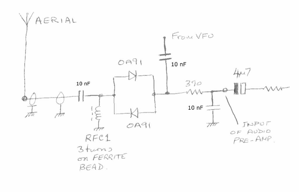
I
have 'issues' with this circuit which I will get to later. But this
is a 'simple' mixer with low component count and low cost. The diodes
can be any germanium types but if they cannot be sourced, use a pair
of general purpose silicon diodes. The circuit will still work though
it may not be as sensitive. I suggest that you make the area around
this part of the receiver clear for 'expansion' as you (like me) will
want to change this for an active mixer...
The VFO Circuit

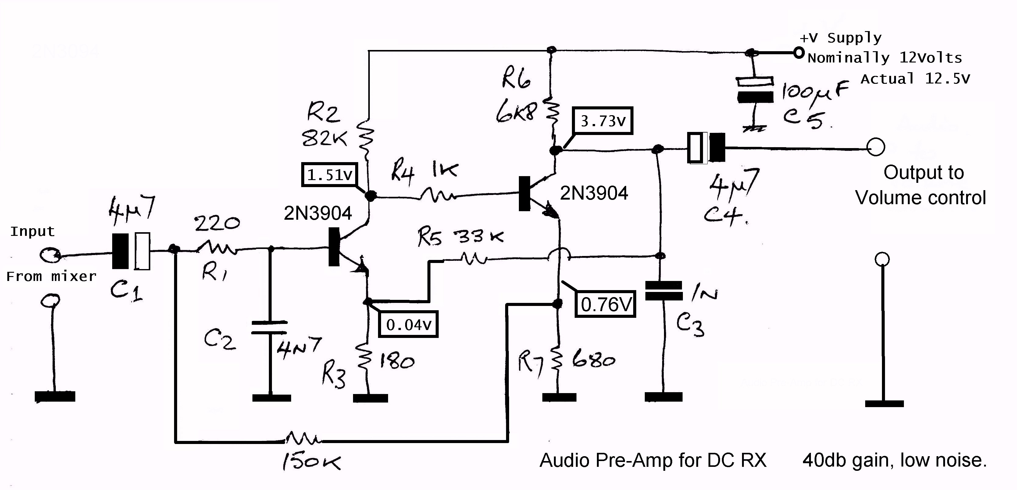
The Audio Amplifier – Low level
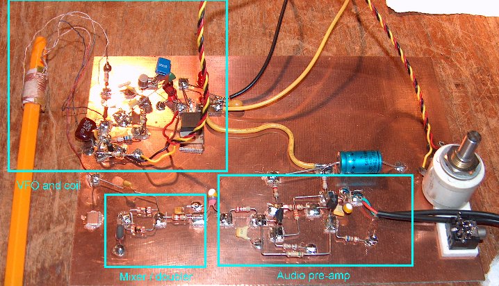
The
DC RX complete
We now have a “working” model. Comprising mixer/doubler and audio pre-amplifier.
Sensitivity is not great; 100 micro Volts at 3.5 MHz for minimum discernable signal.
The receiver is not “noisy” but with an extra gain amplifier stage post volume control, it will provide the required sensitivity.
VFO/VCO results are quite satisfactory.
The Audio Amplifier – high level
This is just an ordinary common-emitter audio stage to boost the audio to a level suitable to feed into an amplified audio speaker set. These are usually to be found 'thrown away' from PC users who get fed up with 'tinny sound' they put out. Bandwidth restricted is just what we need. So grab them when you see them. They come in useful for Morse tone oscillators and direct conversion receivers.
References
TinySDR
http://www.qrz.lt/ly1gp/SDR/
PW 'Colne' Direct Conversion Receiver
by S. Niewiadomski.
Practical Wireless April 1985, page 25.