Direct Conversion Receiver
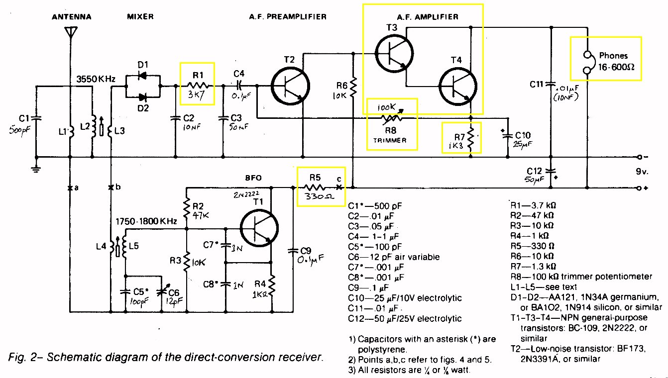
The original circuit diagram
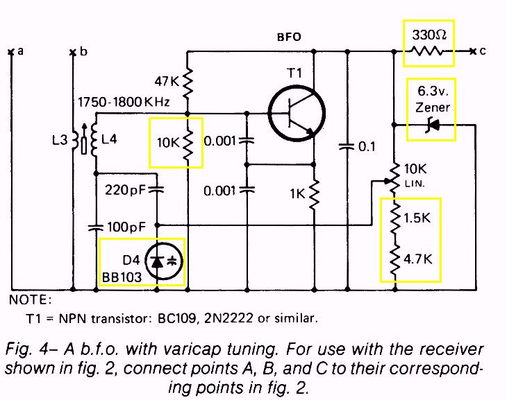
The VFO circuit - Fig 4
DC RX Notes
Referring to Fig 2.
1) Oscillator at half-input frequency, means twice the drift.
2) Two diode mixer will have +/-11 dB conversion loss.
3) R1 (3k7) must be a typo. Probably 3k9.
4) R8 (trimmer pot) bias/gain adjustment is bad practice & probably will destroy T2 if shorted.
5) Darlington on R6 (10k) is rediculous. Input Z of T4 can be 10k+. Redesign this.
6) R7 (1k3) Why not use 1k5 or 1k2?
7) C6 (12pF trimmer) for tuning! Try finding one!
2-18pF trimmer is the only one I have and its not a tuning capacitor.
Rather use an FM transistor radio tuning capacitor in series with 47pF or similar.
8) C6 and L5 tunes to 1750 to 1800kHz, 50kHz in 1800kHz.
small variation in frequency could as easiliy achieved with a varicap diode on stable voltage.
9) OM Chris raised the point re the C7/C8 being 1nF, which he suggested is far too large a value. Suggested 470pF.
Referring to Fig 4.
1) BB103 (D4) probably difficult to find. Rather use 1N4007 taken from a broken energysaver light bulb(globe).
2) 6V3 zeners are available, if you search the country. Replace with 7805 with LED in ground connection.
Two things achieved by this; LED lights when power is on.
A very stable 7 Volt (nominal) source to VFO and varicap tuning diode.
3) 330 Ohm resistor is no longer required.
The Direct Conversion Receiver for 80 metres. After some development.
The DC RX project has progressed quite well over the last couple of weeks.
The original circuit isabove, along with all the comments.
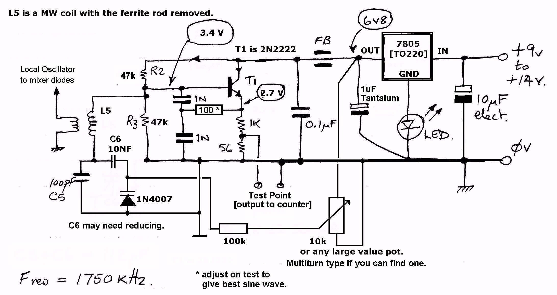
- The VFO which runs at half the input frequency has been tested and finalised.
Its stabiliser is now a 7805 with a led in the ground leg connection.
This provides a very stable 6.8 Volts for the oscillator transistor.
Here is the circuit :-
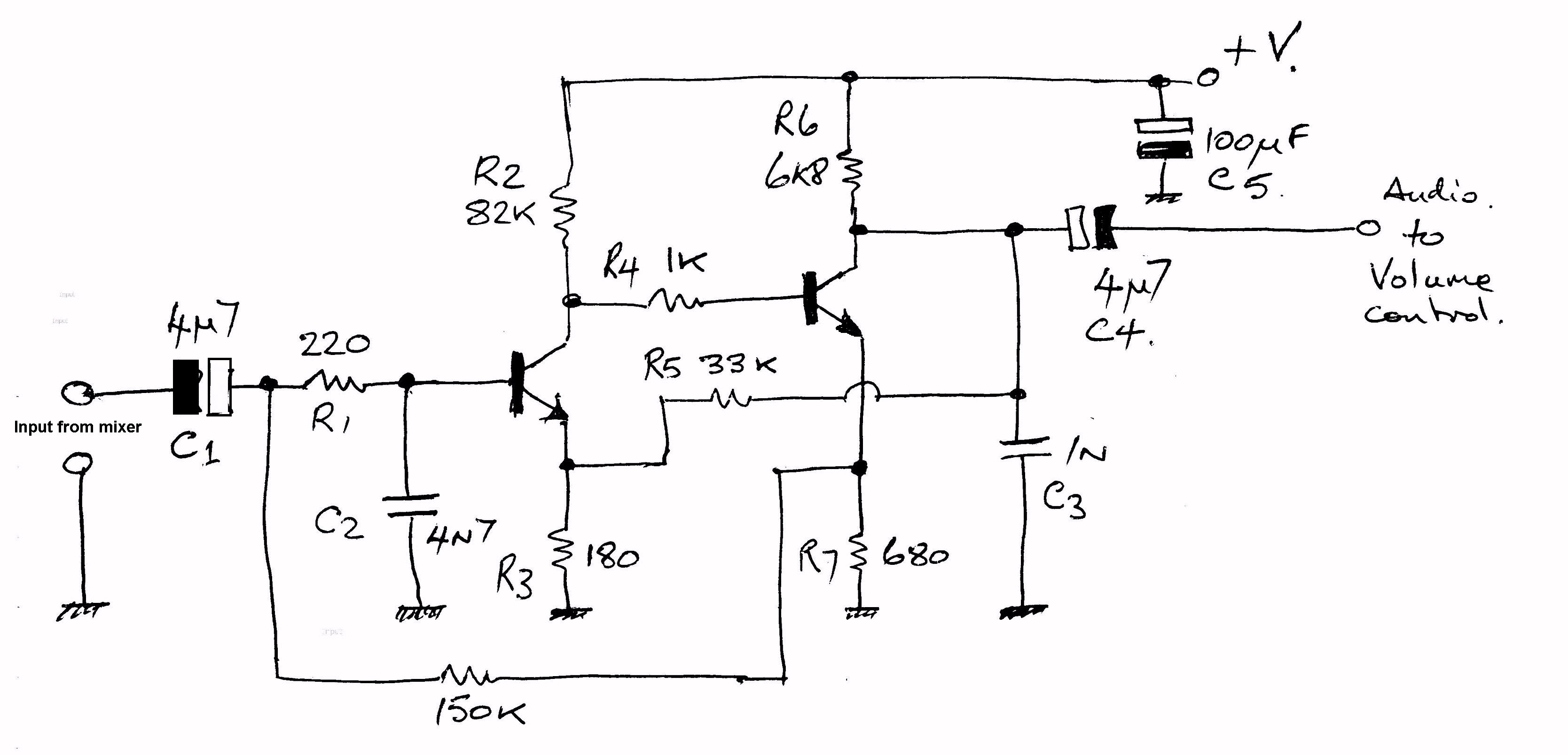
- The low level audio amplifier has been planned, drawn and constructed.
Here is the circuit :-
- The mixer circuit. Using diodes is a very lossy (11dB) method.
Here is the circuit :-
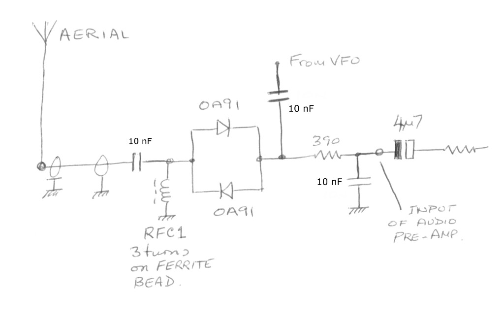
This is where I realised, I hadn't uploaded or drawn a circuit of the mixer!
I have now uploaded a circuit of the mixer. See above. This will at least get you started on the construction.
Any germanium diode will do for the mixer. A silicon diode will also function. But as stated above, the mixer loss is of the order of 11 dB or more.
The Full Working Model
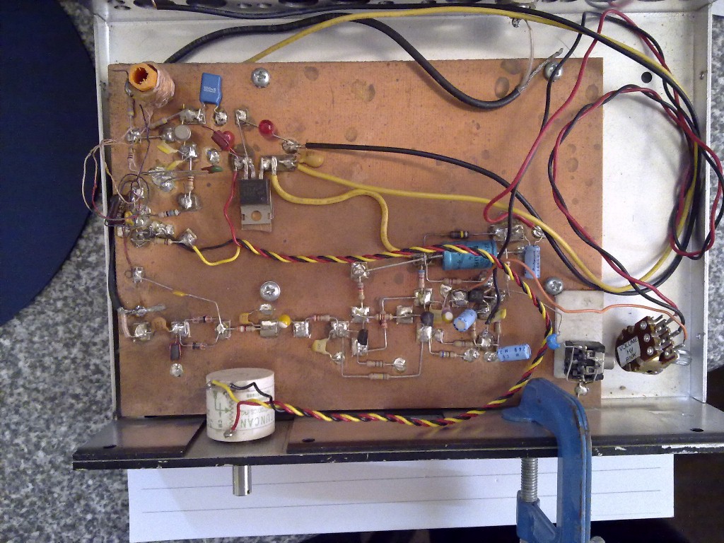
Notes
To be uploaded later...
Results of Testing
To be uploaded later...
GO BACK


