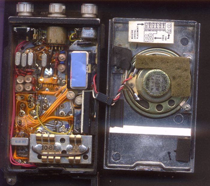
Opening the case shows a burn mark on the case inside. Just above the power transistor. So I jumped to the conclusion that it had suffered damage and would need replacing.
Silly me! Thought it would be that easy! It wasn’t. When I powered it up and had it disassembled for testing, the transistor checked out ok. Fortunately I have the GE manual with circuit diagram. So checking the circuit with power on should allow tracing etc…
Bah! I did not remember that the chassis is not connected to the zero volts or ground of the power supply. Took a few minutes checking the PLL02 chip for incorrect voltages…
Then connected the voltmeter to the ground connection in reality from the supply. Got correct voltages. On closer inspection and taking pictures, I find evidence of somebody messing around inside the radio. Not too happy about this. But persevering with a Tektronix scope and the counter connected to the A channel output produced 10.240 MHz. This from the crystal oscillator that feeds the PLL02 phase-locked loop chip.
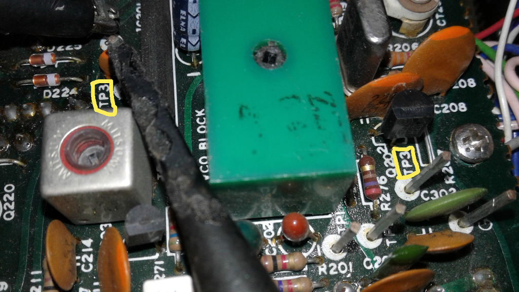
This 16 pin chip replaced the PLL01. According to the GE Manual, the voltages check as correct. So now to check the nicely labelled test points. These are square metal pins that stand proud of the components and have lables on the pcb. I connect the scope probe to test point 3. And get nothing! Put glasses on. Check again. It says TP3. Wiggle scope probe. Nope. Nothing.
A closer look later, I discover that there is another TP3! Put scope probe there and get 20.10497 MHz.
[The major difference between a thing that might go wrong and a thing that cannot possibly go wrong is that when a thing that cannot possibly go wrong goes wrong it usually turns out to be impossible to get at or repair. – Douglas Adams, Mostly Harmless]
See! I am not lying! Two TP3’s!
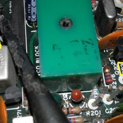
This taking of pictures with the cell-phone camera is quite useful. You can even read the transistor markings as well as the Toko type numbers on the cans.
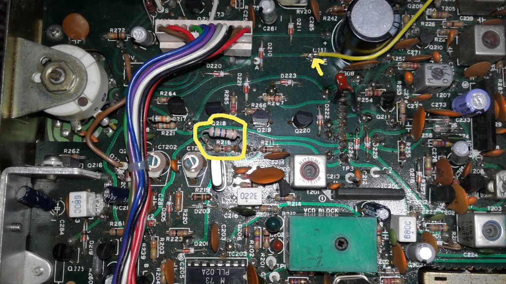
Here is evidence of “fixing” by someone. The yellow wire I believe is to replace a burnt track on the pcb.
Here is the unit opened for inspection. This requires a few unpluggings and untrapping of wires etc.
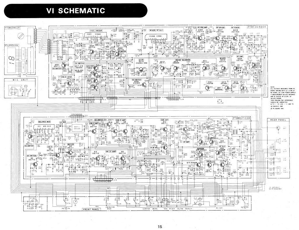
Fortunately I have the manual for the CB. It has a circuit diagram with voltages marked on it. However a word of warning. If you get the PDF of a manual and you want to print the diagram, don’t import the page into GIMP without using the highest resolution possible. Most of these diagrams should be printed on A3. Or use a laser with 600dpi. Especially as the voltages are marked with a microscopic decimal point. Or virtually invisible!
This is the circuit diagram. It is 4.2 MB in size. So don’t download it if you don’t need it.
With lock down, I thought it would give me more time for these repair jobs. Bah!
So the short answer is the CB is still undergoing repairs…
73
John ZS6WL