Categories
Repco / PYE UHF Portable Transceivers
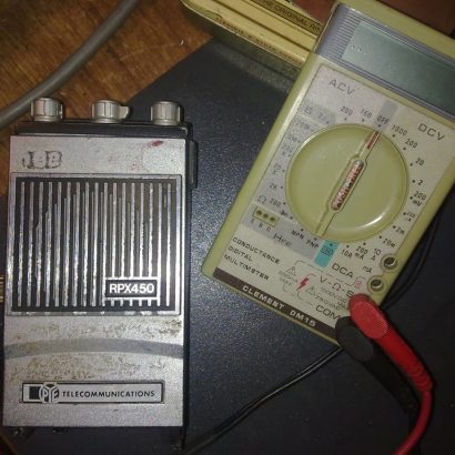
I was “given” these by the club chairman with the expression “Nobody else wants them!”, several years ago. Well after a lot research, I have had to do some ‘digging’ into the ‘guts’. Some disassembly was required and some notes and pictures taken. It has proven to be quite rewarding.
These ex-commercial handie-talkies were obviously used by the Escom power station security personnel. As they were manufactured in the early 1980’s, not much is known about them. PYE and Repco have ‘disappeared’ from the market. Doing a few searches on Google turns up no technical information and certainly no service manuals. However it did turn up adverts for the batteries. They surely cannot be still be in service can they?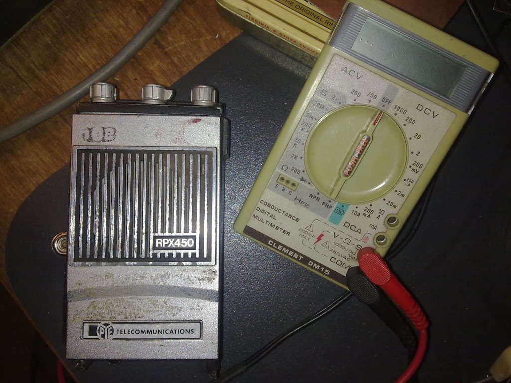
These 1980’s walkie talkies came in two versions. One was a single channel and the other a six channel. Both had positions and places for all the modules. So modules could be substituted. But not the chassis as it had the six pole switch.
I started disassembling some of the modules. The method used would have given my mother grey hairs! I used a plate on the electric stove to heat a module up. Using a pair of pliers I then held the pins joined to the PCB inside the module and pulled the PCB free of the surrounding case. I quickly dropped the PCB and components into a small bowl of water to cool the components and the PCB. A harsh smell of burnt nylon and resin pervaded the kitchen. But I had some modules to investigate.
Working out the technical side
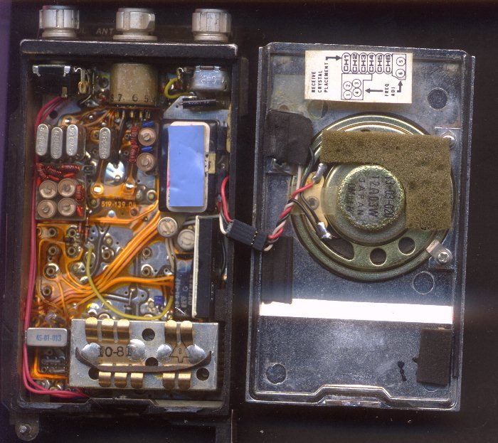
Fortunately for me, one radio still had its receive crystals in five of the six positions. I had already established that the first I.F. was 21.4MHz as I had removed the crystal filter as module. I could read the frequency and details on the can. The one ‘long’ module contains the second I.F. Which is 455 kHz. 
As you can see from the picture above, the 20.945 MHz second local oscillator converts the first I.F. to 455 kHz for the MC3357 chip to demodulate. That blue ‘block’ is the ceramic filter. I was getting quite pleased with myself as I now had a ‘source’ of MC3357’s, even if I didn’t get anything else from these transceivers.
Taking one of the crystals and placing it the “crystal checker”, I got a fundamental frequency for the crystals. These are “third overtone” types and run in the transceiver around 48-52 MHz. But when in the “crystal checker” they run at a third of that frequency. Typically around 16 to 17 MHz.
The receive and transmit frequencies are embossed on the rear panel of the transceiver. So it was fairly easy to work out the multiplier ratio for the chain. This resides in two modules – now called ‘TX x9 multiplier’ and ‘RX x9 multiplier’. Both have test points on them. So you can adjust the circuitry. But connecting a meter to them is another matter. Not much wire is available at these point. Touching them with a test prod produces a reading on the meter. But if you also want to adjust something, you need another pair of hands.
Why ‘times nine’? Well its fairly easy to make a times three multiplier amplifier with a transistor. Ironically it is not so easy to make a times two without using a diode or similar. So the overall multiplier is ‘times nine’. That’s two stages of ‘times three’ giving ‘times nine’.
Making them work for a living
After a long pause in this project, I took them up recently as I could use a 403 MHz receiver. Of course I don’t have a suitable crystal. But I do have crystals that could be persuaded to work ‘close by’ in frequency. Then I could adjust or order a suitable crystal. The thought did occur to me that the DDS project could provide an accurate “Local Oscillator”. Or I could try and make a voltage controlled oscillator at the right frequency. But the first thing to do is to get the transceivers to work using the crystals I had found. If the receive sides worked, I could adapt them to suit, knowing that the circuitry worked.
The first crystal I found to be ‘close by’, was a 46.275 MHz crystal. This when multiplied by nine gives a local oscillator of 416.475 MHz. Subtracting the I.F. of 21.4 MHz, gives an input frequency of 395.075 MHz.
I then had to work out which position the switch was in for the first channel. Whilst the diagram on the plate gives the position of the crystal, the switch has no markings! Fully counter-clockwise is the correct position. Plugging one of the existing crystals in, I checked for noise on channel. And much less noise on the ‘dead channel’. That is the one without a crystal and therefore no local oscillator. All good there. So I switched on the signal generator and tuned carefully across the 457 MHz region. I got an output blip and zeroed in. Finally I got it spot on. With the output from the signal generator at full output, transmitting into a piece of wire a centimetre long, I reduced the output level. I went down in level a long way. Boy was the receiver sensitive!
So I plugged the 46.275 MHz crystal in to the second position. I switched the switch to channel two. I got a very quiet radio…
The adjustment of the receive multiplier module requires a small (< 3 mm) blade screwdriver. Preferably of non-ferrous nature. Of course when you look for one, they all hide. So I picked up a watchmakers screwdriver of the ‘right sort’ and used that. The noise level jumped up. I carefully tuned the signal generator at full output and got a blip. Then I tuned it in for a clean tone at 400 Hz. 1 kHz is OK, but not for long periods. Carefully tuning the multiplier, I got the order of sensitivity that I desired. So the receiver can do the job!
I went to the garage to get a few more units to test. I then set them up on the bench with a small 12 Volt power supply. The first one I tried to get working was very quiet. (Of course!)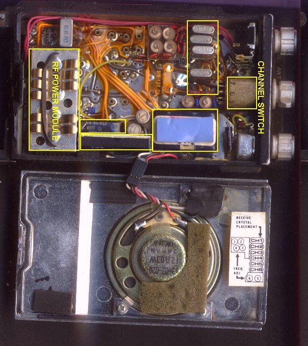
So was the second one. What I had I done wrong? I checked everything carefully but nothing said to me that I had done them wrong. You can see from the picture above, I came across the tone decoder/encoder and gate modules after I had compared the one working set I had. This one had a wire link where the ‘Tone gate module’ was. When I prised loose the module and substituted a wire link between sockets, I was rewarded with a lot of noise.
Getting to transmit at UHF
None of the transceivers had crystals for transmitting. Over the years, I have never thrown a collected crystal away. So I went looking in the container marked “Crystals”. From a UHF hand held many moons ago, I had retrieved some transmit crystals. Well one of them was ‘close by’. It even had 467T075 on it in microscopic numbers and letter. It also fitted the socket…
Using a signal strength meter I had built last century, I tried transmitting into a short piece of wire. Whoopee! I had a working transmitter that could make the meter read two thirds of full scale. A careful tune up of the x9 transmitter multiplier gave me a maximum reading. Unfortunately this is not realistic. For one the piece of wire was nowhere near a real quarter wave monopole. Secondly the output aerial – probably was a “rubber ducky” – was missing on all the radios. The screw fitting inside the radio is soldered to a 2.5mm jack socket which has the short length of hard-line coax feed from the transmit/receive relay, it is about a 5 or 6mm thread. I had no means of connecting a power meter to this output. So I removed the aerial mounting for inspection. I shall be connecting a ‘real coax connector’ some time soon. I shall be letting you know in a later article how I got on.